Technical Implementation Details
The implementation of fluid rendering is based on the classic article by Simon Green: Screen Space Fluid Rendering for Games. You can refer to this paper for more in-depth information as I will not always give too much detail for some steps.
Note: in the images above and below, the particle positions are from a pre-computed water simulation (SphereDropGround Package).
Overview
As the title implies, this is a screen space technique, which in Babylon.js is a number of 2D post-processing applied after rendering the 3D scene into a 2D texture.
The inputs are simply a list of 3D coordinates representing particles. These particles can be generated from any source: a regular particle system (ParticleSystem / ParticleSystemGPU), a real fluid simulation or even custom user code. As long as you are able to produce a list of 3D coordinates, you can use the fluid renderer to display them as a fluid.
Depth rendering
The first step is to treat each particle as a sphere and project them as circles to generate their depths in a texture. Strictly speaking, a 3D sphere can be projected into an ellipse in a 2D perspective projection, but in practice sticking to circles works well and is more lightweight/computationally easy.

Here is a diffuse rendering to better see the particles:
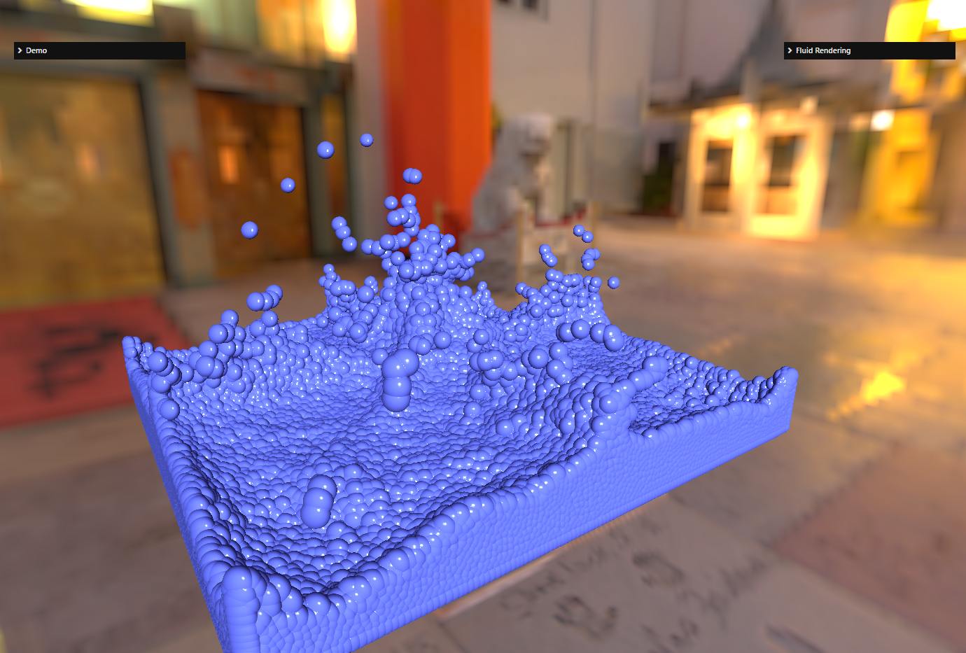
The depth must be a linear depth for the blur post-processing to work as intended (see next step)! Thus, the depth texture is created by recording the z-coordinate of the view space of each projected point of the sphere. The shaders used to generate this texture are particleDepth.vertex.glsl / particleDepth.fragment.glsl.
The normals used for the diffuse (and final) rendering are computed thanks to the depth and the uv coordinates. The depth of the view space as well as the uv coordinates are converted to NDC (Normalized Device Coordinate) space and these coordinates are transformed to view space by multiplying them by the inverse projection matrix. We will describe the calculation that converts Z from view space to NDC space a little later in the text as this is a question that comes up often in the Babylon.js forums.
Depth blurring
Depth blurring is the important step of the technique, this is how you get the "fluid" look in the final render:
| Without blurring | With blurring |
|---|---|
Without blurring  | With blurring 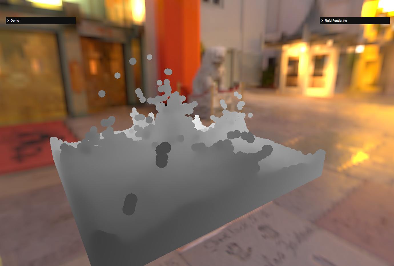 |
Without blurring  | With blurring 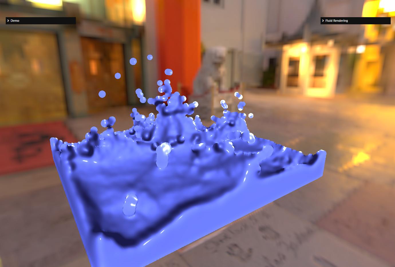 |
As explained in 1 slides 20-31, a standard 2D Gaussian blur will not be appropriate, as you may end up blurring particles that are very far away in the z-dimension if you stick only to the 2D dimension of the texture. A bilateral filtering takes into account the Z-depth of each texel to be blurred and will apply more blur for small Z-differences and less/no blur when Z-differences are too large. Moreover, the filtering must make sure that we blur the same amount depending on the distance to the camera: if the particles take up a large part of the screen (say 200x200 pixels) because they are close to the camera, the size of the filter kernel must be larger than if they are far away (say 4x4 pixels): the size of the filter kernel must fit the depth of the texel we are blurring. We will describe the calculation later in this document.
Note that for performance reasons, the bilateral filtering is performed by first applying a filter in the X dimension and then another one in the Y dimension. This is not mathematically correct because bilateral filtering is not separable. Doing two passes produces some artifacts but they are normally not visible/acceptable and it would be too GPU performance consuming to do otherwise anyway, so it's a tradeoff we pay for better performance at the expense of quality.
The shader used to implement bilateral filtering is bilateralBlur.fragment.glsl.
Reference 2 helped me a lot to configure this shader correctly (especially to adapt the kernel size to the projected particle size).
Basic rendering
Once we have a blurred depth texture, we can render the fluid.
As explained above, the normal is computed using the depth and uv coordinates (more details in 1 - slides 17/18).
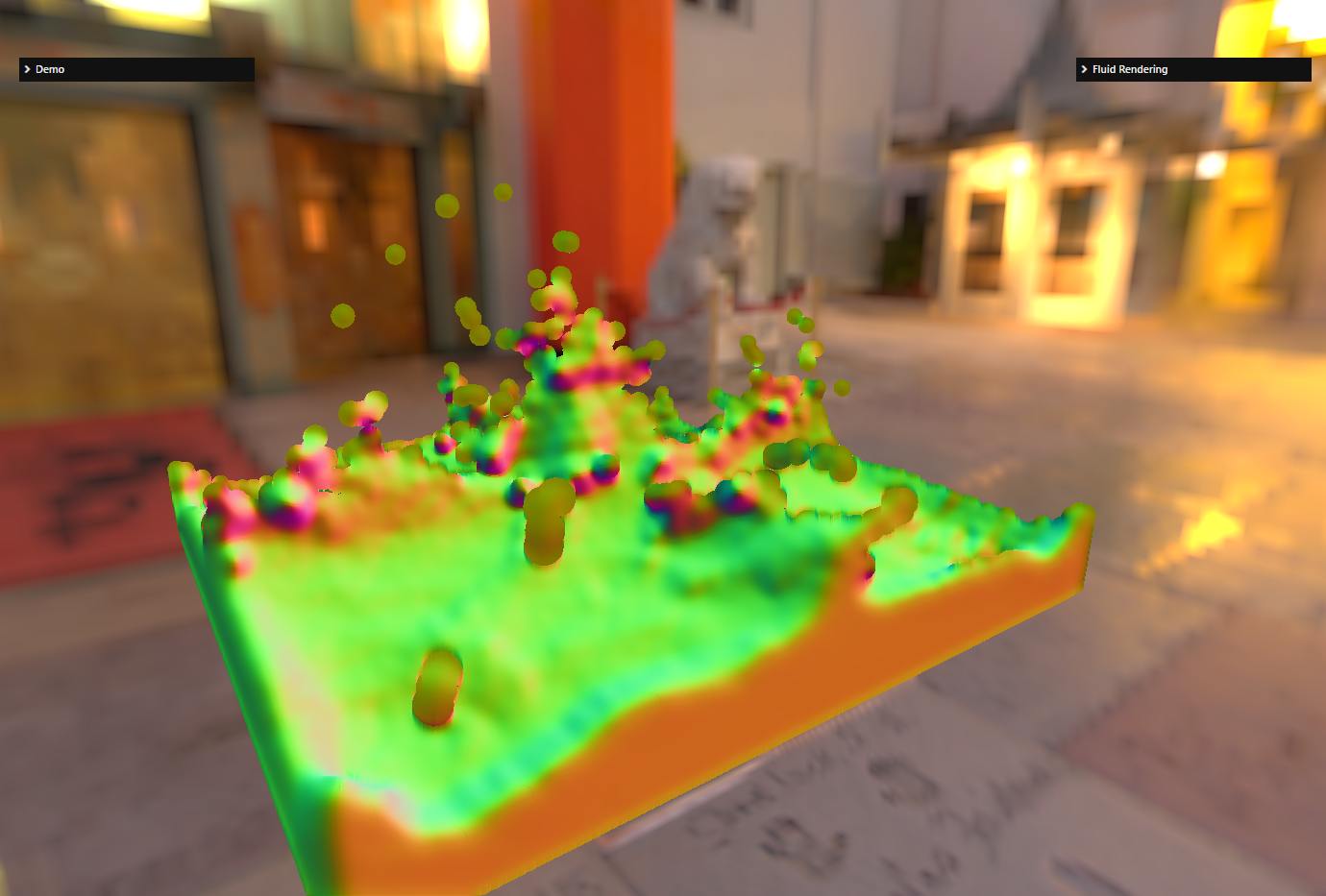
Here are the normals computed for the example scene:
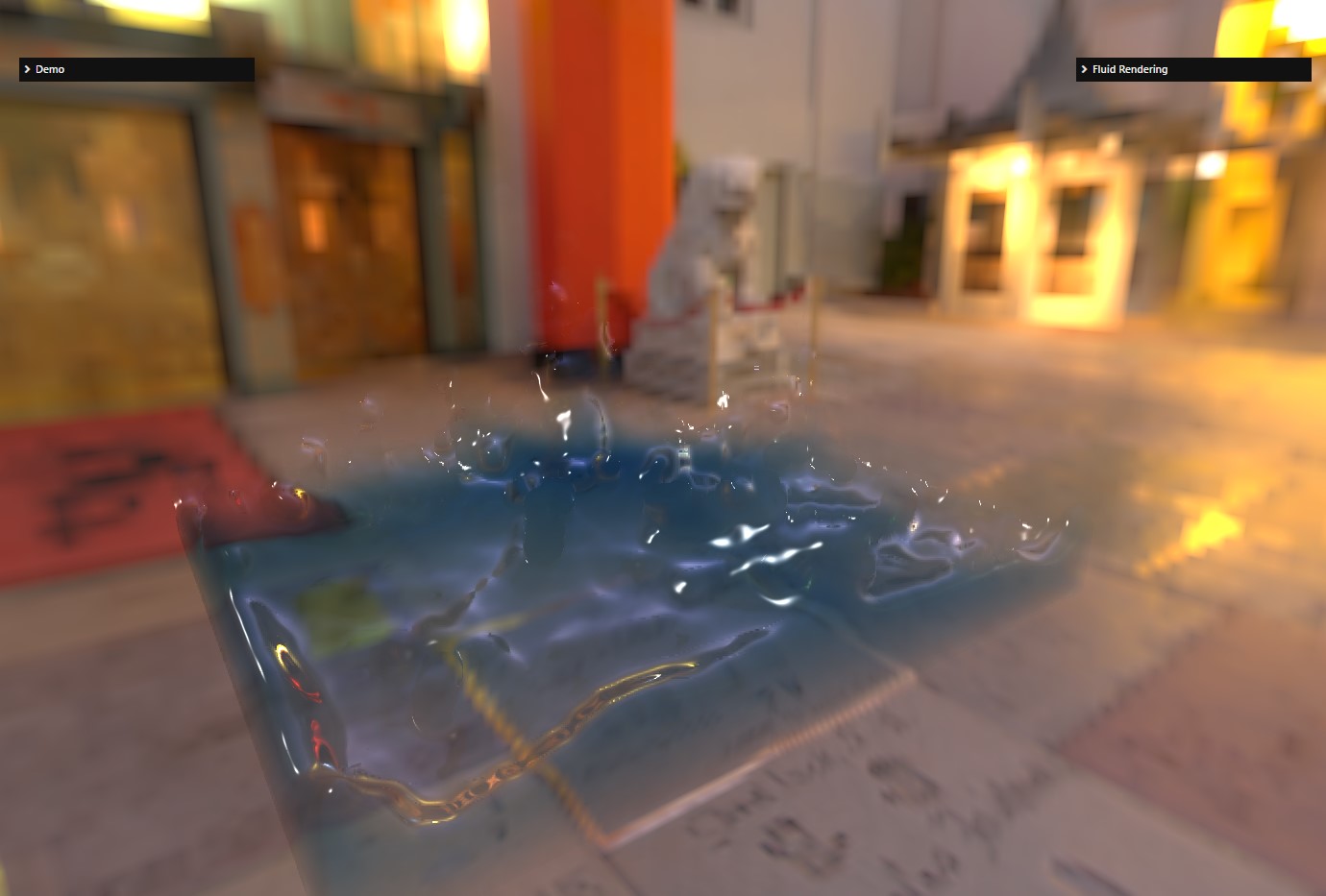
For fluid surfaces, it is important to implement the Fresnel effect, which is responsible for higher reflections at grazing angles (again, see 1 - slide 39). Furthermore, for a more accurate rendering, we use Beer's law to calculate the refractive color, which states that the light intensity in a volume decreases exponentially as the light passes through it: I=exp(-kd) with d being the distance traveled by the light and k the absorption factor (which depends on the color of the volume). For a basic rendering, we can use a fixed value for d (the thickness of the volume) for the whole volume. You get something like :
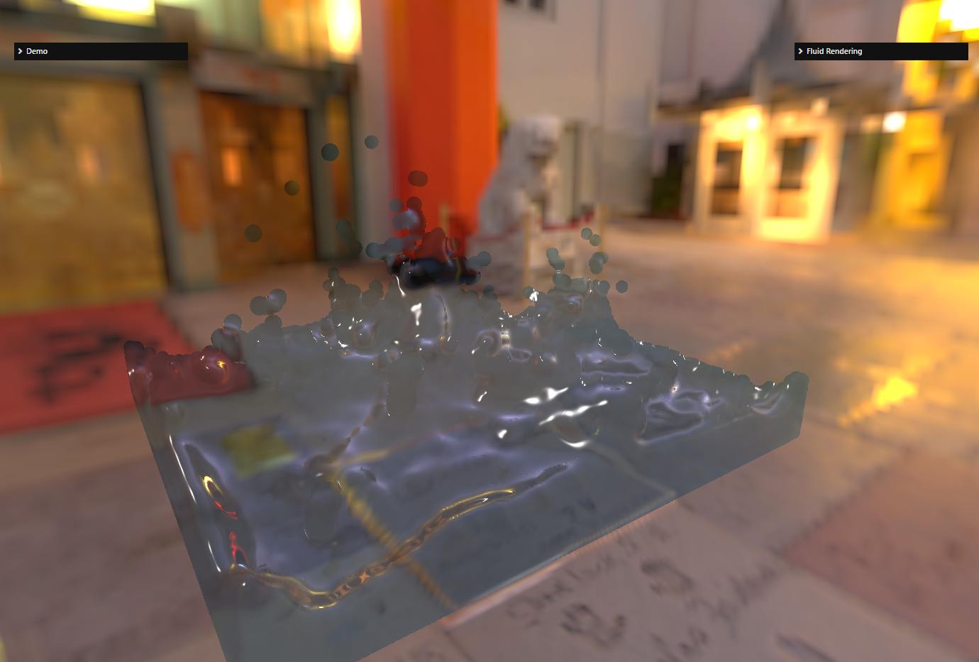
The shader used to implement the final fluid rendering is renderFluid.fragment.glsl.
We can do better by calculating a thickness for each texel (see next step), but if you are limited by the GPU, this is a cheaper way to render fluid surfaces.
Improve rendering with a thickness texture
Instead of using a fixed thickness for the whole volume, we can try to calculate it for each texel. This is done in the same way as for the depth texture, but instead of generating a depth value for each point of the sphere (particle), we write a thickness value. To accumulate the values, we activate the alpha blending (with the ADD function) and deactivate the Z test so that all particles can contribute to the texture: even if a particle is not visible from the camera (because it is hidden behind other particles), it should still contribute to the thickness calculation. Then, in the final rendering pass, we use this texture to retrieve the thickness value used in Beer's law equation.
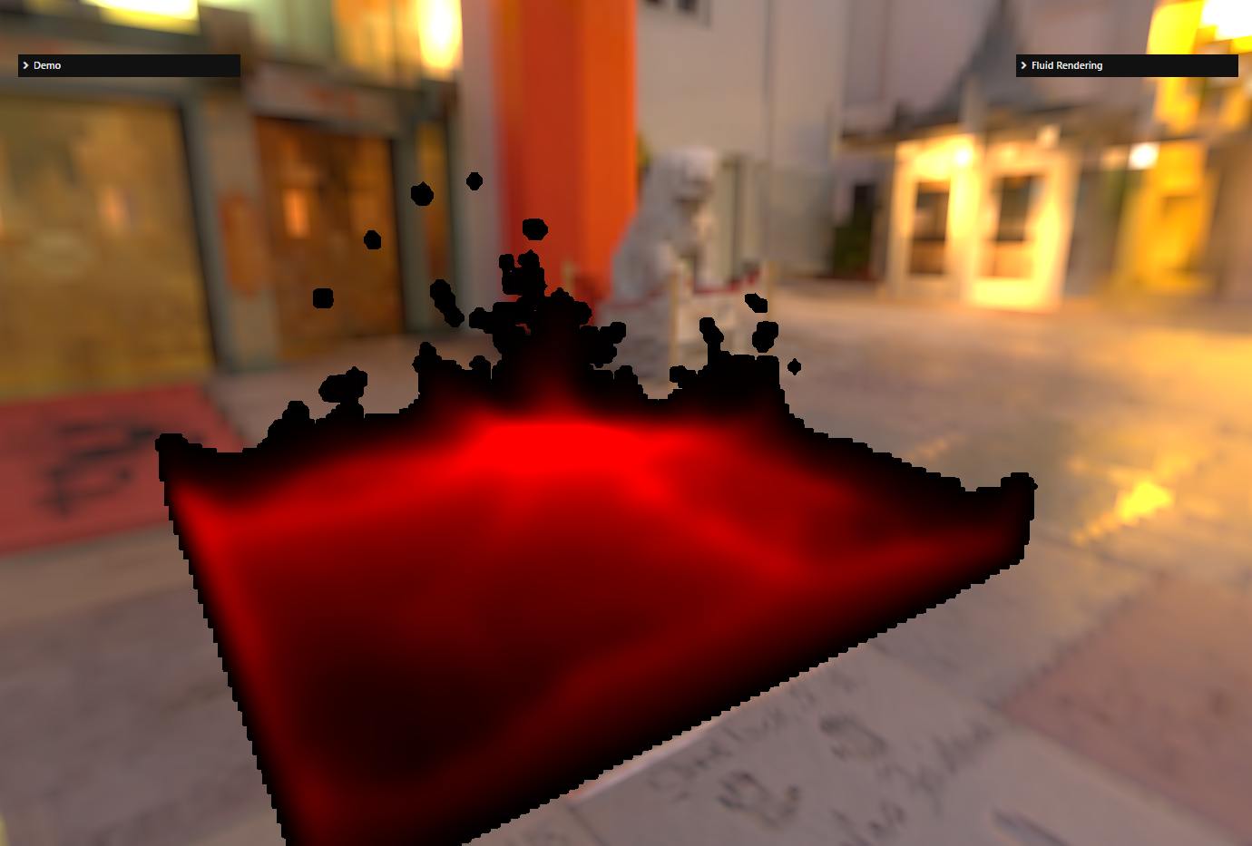
Thickness texture:

As you can see, the resolution is low (the thickness texture is 256x256 in this screenshot). It's ok because the thickness is a low frequency signal, the values are smooth and do not vary much from point to point. In any case, you should try to use as small a texture as possible for the thickness texture as it is quite fill rate intensive. Also, as with the depth texture, we apply a blur to this texture. This time, however, a standard 2D Gaussian blur is sufficient, we do not need a bilateral filtering.
Blurred thickness texture:
Final rendering with a blurred thickness texture:
Et voilà! This is what you need to do to render a set of particles as a fluid surface.
Using a diffuse texture
This is an additional step that is not described in 1.
Instead of using a single color for the entire fluid volume, a different color can be used for each pixel by means of a diffuse texture. This texture is generated by rendering the particles as spheres (like the depth/thickness texture) but using a vertex color associated with each particle to draw the sphere. So the inputs are now a list of 3D coordinates + a list of colors.
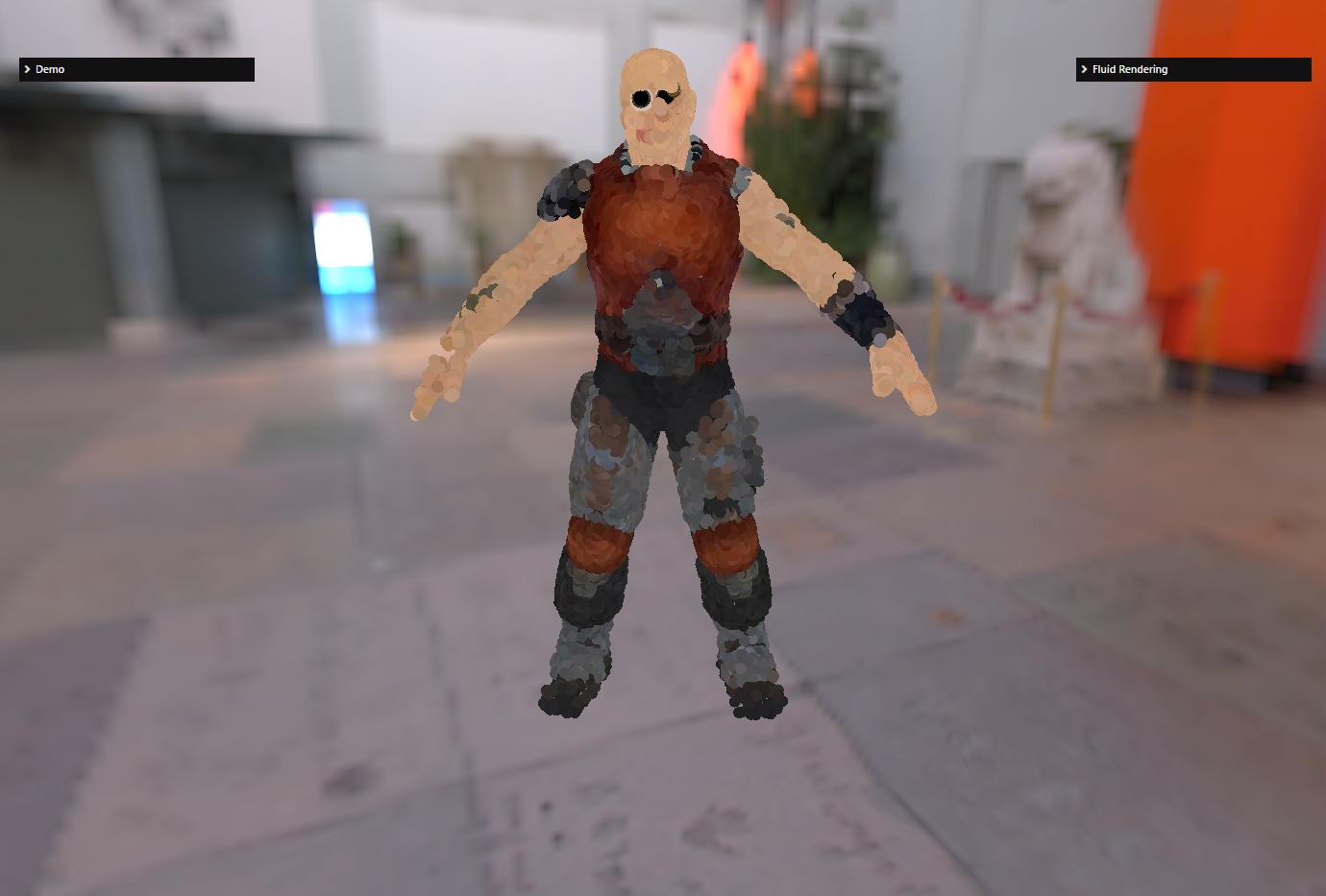
For example, here are two renderings of the "Dude" model as a fluid, with and without the diffuse texture:
| Without the diffuse texture | With the diffuse texture |
|---|---|
Without the diffuse texture 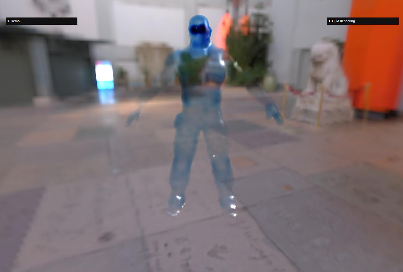 | With the diffuse texture 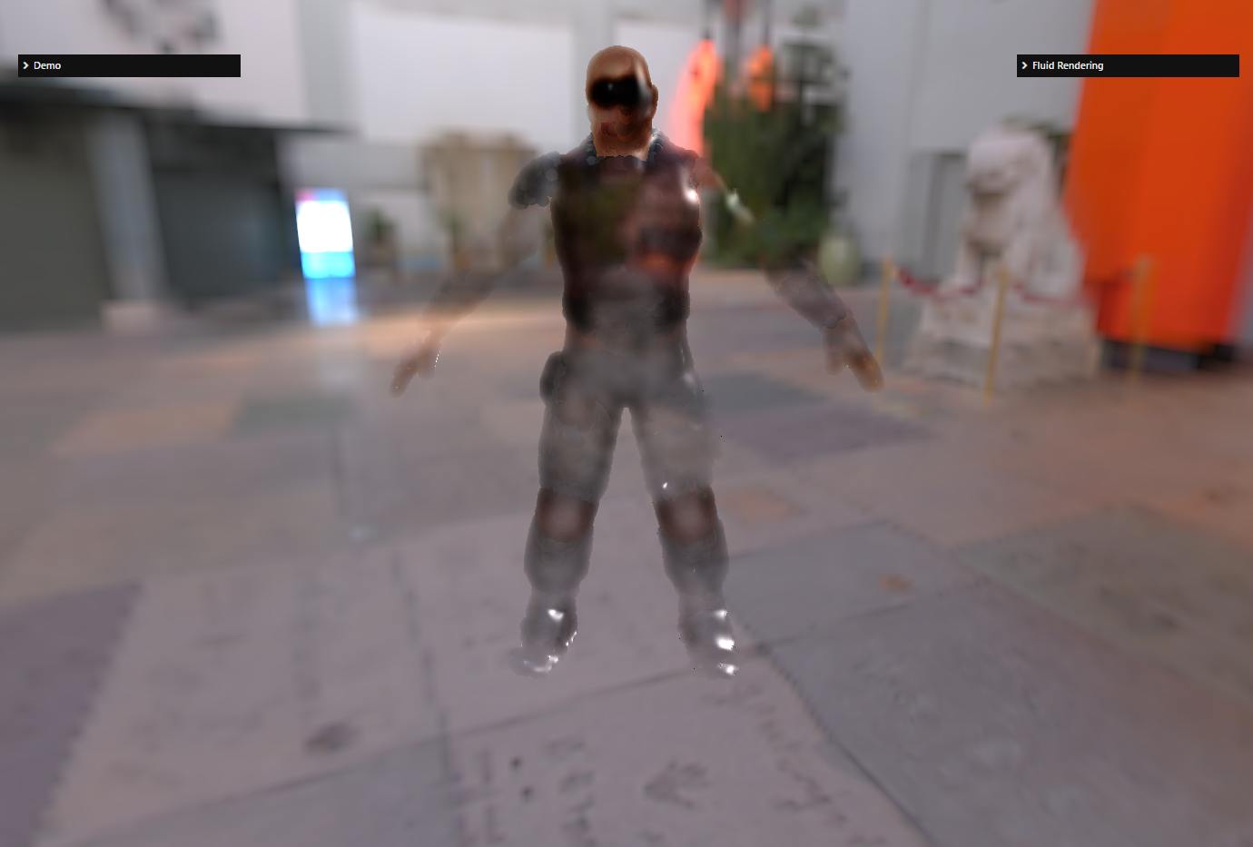 |
The generated diffuse texture :
The list of 3D coordinates for the dude was generated using the PointsCloudSystem class, which can generate points distributed over a mesh and is also capable of generating vertex colors for these points by sampling the diffuse texture of the material.
The shaders used to generate this texture are particleDiffuse.vertex.glsl / particleDiffuse.fragment.glsl.
The following section will go into more detail on some of the steps described and others that I ignored (such as including the fluid in an existing scene).
Implementation details
Converting the view depth to NDC depth
In the final render shader, we need to convert a view depth to NDC depth several times. Here is how to do this conversion.
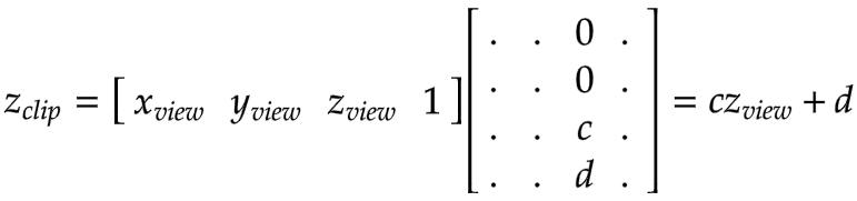
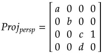
The projection matrix used to transform view space points to clip space in Babylon.js is (perspective projection):

Thus, the z-coordinate in view space is transformed to clip space as :
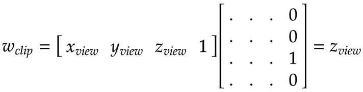
Finally, the z-coordinate of the clip space is transformed into NDC space by dividing it by the w-coordinate of the clip space :
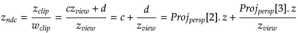
This is the formula used in the rendering shader:
Calculation of the kernel size for the bilateral filter
As explained above, we need to use a kernel size for the bilateral blur so that the particles are blurred in the same way when they are close to or far from the observer.
To this end, we need to make the kernel size depend on the projected size (on the screen) of the particle: a particle A that projects to twice the number of pixels of particle B must have a kernel size twice as large.
So, let's project the coordinate of the particle from view space to screen space (note that we are doing the calculation on the Y coordinate, not X, because the b coefficient is a bit simpler than the a coefficient in the projection matrix):
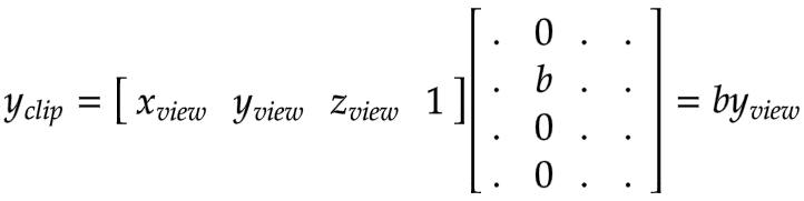
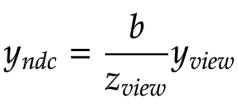

Thus, the screen size of the projected particle is (d being the diameter of the particle):

Note that everything can be precomputed, except for Zview :
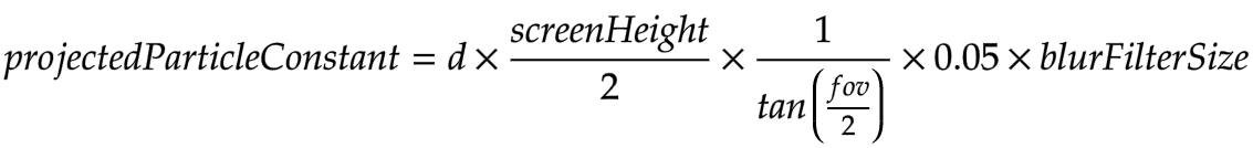
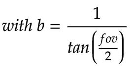
blurFilterSize is the user parameter used to adjust the blur and 0.05 is a scaling factor so blurFilterSize = 10 is a good default.
To calculate the kernel size, the bilateral blur shader simply does :
Integrating the fluid into an existing scene
The problem we want to address here is that the fluid needs to take into account existing objects in the scene and be obstructed when objects are in front of it.
So, in fact, we need to take into account the depth buffer of the scene when generating the depth and thickness textures of the fluid. However, we only need to add this support when not generating the thickness texture, because when the fluid is occluded, the value of this texture will be 0, which is tested in the fluid rendering shader:
#ifndef FLUIDRENDERING_FIXED_THICKNESS if (depth >= cameraFar || depth <= 0. || thickness <= minimumThickness) {#else if (depth >= cameraFar || depth <= 0. || bgDepth <= depthNonLinear) {#endif vec3 backColor = texture2D(textureSampler, texCoord).rgb ; glFragColor = vec4(backColor, 1.) ; return; }As you can see, we test that thickness is at least equal to minimumThickness to avoid returning prematurely: this is to be able to skip isolated fluid particles that are too thin (minimumThickness is a parameter the user can set).
You can also see that we handle a second case where the thickness is fixed (so FLUIDRENDERING_FIXED_THICKNESS is defined) and we do not use a thickness texture. In this case, we rely on a test between the depth value of the scene depth buffer (bgDepth) and the fluid depth (depthNonLinear). We could have also used this test in the thickness texture case, but what we did is probably faster because we limit the fill rate of the thickness texture where the fluid is occluded, and we also avoid a search in an additional texture (the scene depth buffer).
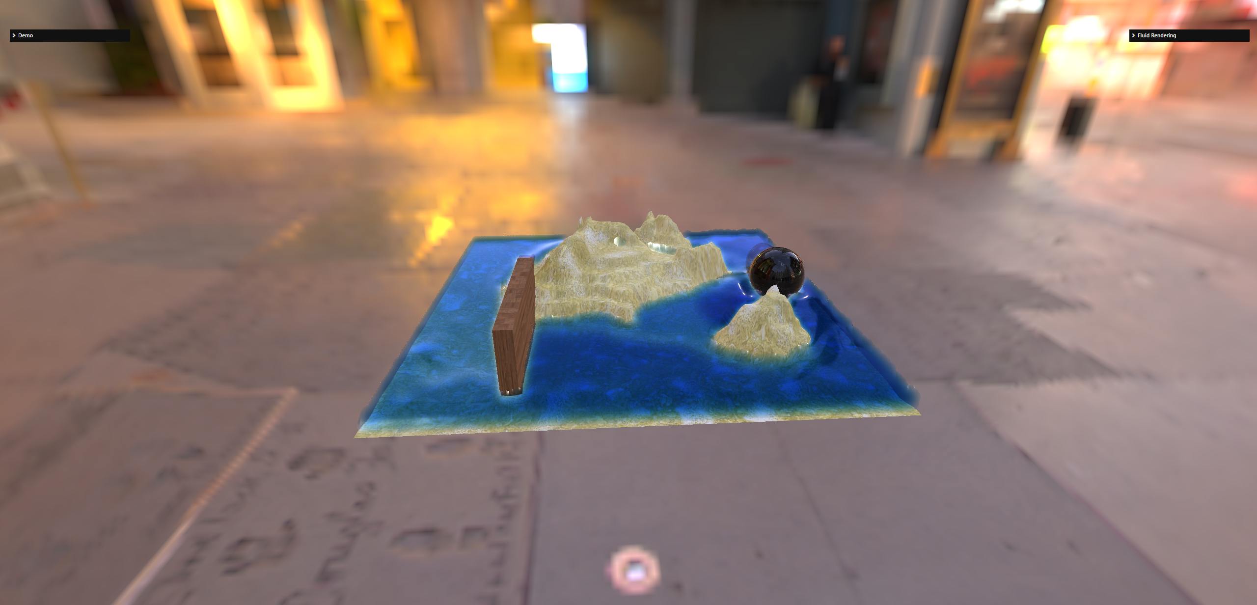
For this scene:
Here is what you get for the thickness texture without and with the scene depth buffer handling:
| Without scene depth buffer handling | With scene depth buffer handling |
|---|---|
Without scene depth buffer handling 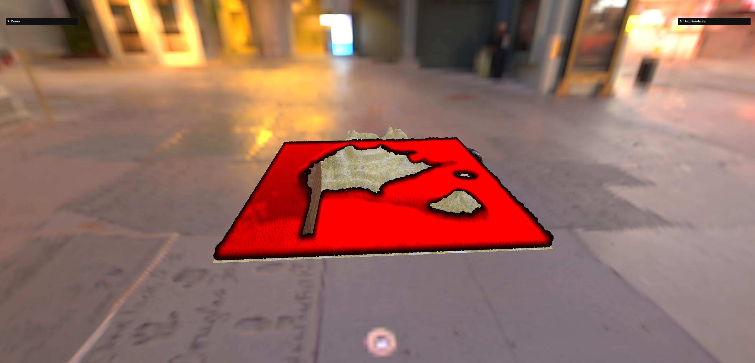 | With scene depth buffer handling 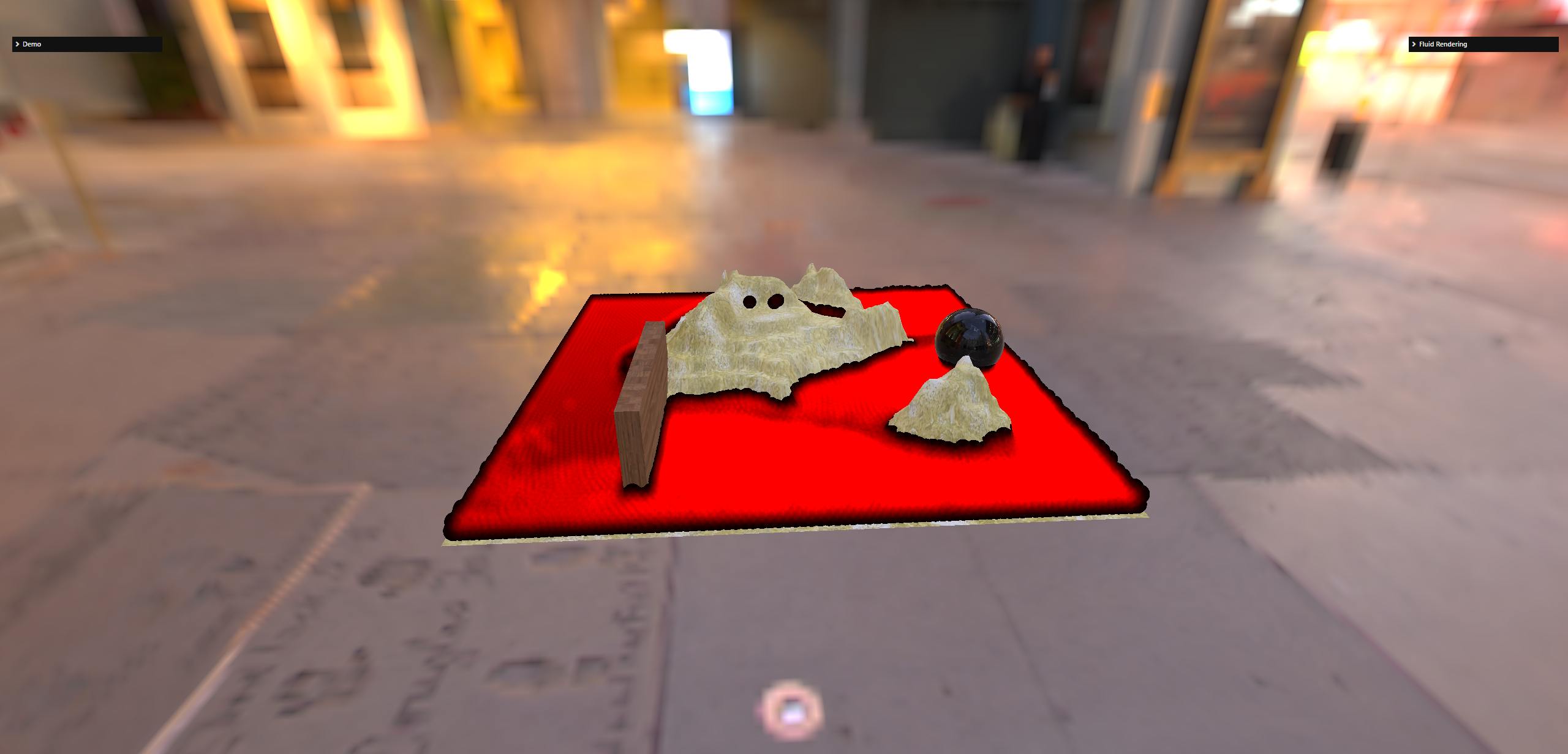 |
So how do we generate and use the scene depth buffer when generating the thickness texture?
We need to understand how post-processes work in Babylon.js to be able to generate this buffer and use it in the generation of the thickness texture.
Post-processes in Babylon.js
A post-process is simply a render target texture (RTT) + a shader. The shader is run on the texture and the result is generated in another texture.
The tricky part here is understanding that the texture the post process writes to is the RTT of the next post process in the chain!
So, for the ith post process in a chain of n post processes:
- its RTT is filled by the post process at step
i-1 - it runs its shader on its RTT and outputs the result to the post process RTT at step
i+1.
Now you can see that there is a problem for the first and last post process because i-1 and i+1 are not defined, respectively.
These special cases are handled as follows:
- the RTT of the first post process is filled by rendering the scene. This means that when there is at least one post-process, instead of rendering the scene in the default frame buffer (i.e. the screen), the system renders the scene in the RTT of the first post-process in the chain.
- the last post-process renders into the default frame buffer (i.e. the screen).
This is all we need to know in order to retrieve the scene depth buffer.
Using the scene depth buffer when generating the thickness texture
As we explained above, the first RTT of the post-processing is used to render the scene. So, if we enable the generation of the depth texture on this RTT, we can retrieve it and reuse it later when generating the thickness texture.
This is done in the following way:
const firstPostProcess = camera._getFirstPostProcess() ;if (!firstPostProcess) {    return ;}
firstPostProcess.onSizeChangedObservable.add(() => {    if (!firstPostProcess.inputTexture.depthStencilTexture) {        firstPostProcess.inputTexture.createDepthStencilTexture(            0,            true,            this._engine.isStencilEnable,        ) ;    }}) ;
We do this in the onSizeChangedObservable event because this RTT can be recreated if you resize your browser, for example. This event is called after firstPostProcess.inputTexture is recreated, so it is safe to call createDepthStencilTexture at that point.
Using the depth texture generated in this way when generating the thickness texture is simply a matter of doing :
firstPostProcess.inputTexture._shareDepth(thicknessRT) ;where thicknessRT is the RenderTargetWrapper used to generate the thickness texture.
However, there is a subtlety here: we allow the user to use a different size for the thickness texture than for the scene! Thus, it is possible that thicknessRT does not have the same width/height as the RTT of firstPostProcess.inputTexture. In this case, you will get an error when trying to use the scene depth buffer with thicknessRT because it is not allowed to use different sizes for the depth texture and the normal output rendering texture.
So we have to resize the scene depth texture to match the dimensions of thicknessRT before we can use it. There is a little helper class that does this (FluidRenderingDepthTextureCopy) but it's not totally straightforward because you are not allowed to do a simple texture copy: copying depth textures is not allowed (neither in WebGL nor in WebGPU). So you have to render a texture and set gl_FragDepth to the value of the source depth texture (reading from a depth texture is allowed in a shader) to write to the output (correctly sized) depth texture.
Use particle velocity to simulate foam
This is an experimental feature at this time.
When enabled, the particle velocity is written to the depth texture along with the depth (depth is in the red component, (magnitude of) velocity in the G component). It is blurred in the same way as the depth by the bilateral blur.
In the final rendering shader, it is simply used to change the color to white when the velocity is above a given (hard-coded) limit:
vec2 depthVel = texture2D(depthSampler, texCoord).rg ; ...#ifdef FLUIDRENDERING_VELOCITY float velocity = depthVel.g ; finalColor = mix(finalColor, vec3(1.0), smoothstep(0.3, 1.0, velocity / 6.0)) ;#endifReferences
- Screen Space Fluid Rendering for Games by Simon Green
- Implementation of the i3D2018 paper "A Narrow-Range Filter for Screen-Space Fluid Rendering" by Nghia Truong. The two-sided filtering is implemented in filter-bigaussian.fs.glsl.