Node Geometry
What Is Node Geometry
The NodeGeometry feature was inspired by Blender Geometry Nodes where you can use a node system to build geometry procedurally. Think about it like a postprocessing system for geometry. Ultimately it produces a geometry but with a procedural approach.
Why Use Node Geometry?
Several reasons come to mind:
- The cost of downloading assets on the web is a strong limiting factor. Procedural data can help solve that by limiting the download to the core pieces that are assembled later by the
NodeGeometrysystem - The system is dynamic and can produce infinite variants at run time. While there are many digital content creation tools that can create procedural meshes with the same infinite possibilities, the limiting factor again becomes downloading assets created offline. Examples would be terrain or vegetation generation.
- It allows a new way of modelling in Babylon.js by assembling core shapes and playing around with a node system
Example
Here is a complete example of an advanced NodeGeometry which is used to generate a city with different buildings:
How to Use
The NodeGeometry class is an utility class, meaning it is autonomous and does not require access to an engine or a scene. So instantiation is pretty simple:
const nodeGeometry = new BABYLON.NodeGeometry("my node geometry");Once created, the system will expect you to create a flow from a source to an endpoint. In a nutshell, the NodeGeometry will process VertexData structure (See more in the section Create Custom Meshes From Scratch).
By default, the NodeGeometry system supports the following sources:
- Box
- Capsule
- Cylinder
- Disc
- Grid
- Icosphere
- Mesh
- Plane
- Sphere
- Torus
Here is for example a complete graph that simply generates a sphere:
// Create node geometryvar nodegeo = new BABYLON.NodeGeometry("nodegeo");
// Create source spherevar sphere = new BABYLON.SphereBlock("sphere");
// Create outputvar output = new BABYLON.GeometryOutputBlock("geometryout");nodegeo.outputBlock = output;sphere.geometry.connectTo(output.geometry);
While this example is very simple, it isn't hard to imagine how adding more operations to the graph will present opportunities to alter the geometry flow which is represented by the VertexData provided by the source node. Updating that VertexData will influence the geometry passed to the GeometryOutputBlock.
The GeometryOutputBlock will collect the final VertexData that can then be used to generate a mesh:
// Build and instantiate meshnodegeo.build();var mesh = nodegeo.createMesh("nodegeomesh");Updating the Geometry Flow
Now that we have the basics in place, we can start to introduce blocks which will update the data.
The simplest blocks will be the setXXX blocks which focus on generating data for a specific mesh component like positions, normals, colors, uvs, etc.:
- setPositionsBlock
- setNormalsBlock
- setTangentsBlock
- setColorsBlock
- setUVsBlock
These blocks are updating the VertexData by generating an entry per vertex inside the geometry. For that specific reason you can imagine them like a loop going through the list of vertices and inserting data from their input.
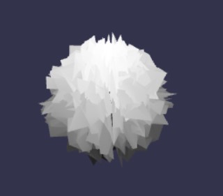
One way to insert data into the block is to simply use a RandomBlock which will generate a random value. In this example we are setting random positions for each vertex in the sphere:
// Create node geometryvar nodegeo = new BABYLON.NodeGeometry("nodegeo");
// Create source spherevar sphere = new BABYLON.SphereBlock("sphere");
var setPositions = new BABYLON.SetPositionsBlock("set positions");sphere.geometry.connectTo(setPositions.geometry);
var getRnd = new BABYLON.RandomBlock("random");var rndMin = new BABYLON.GeometryInputBlock("rndMin", BABYLON.NodeGeometryBlockConnectionPointTypes.Vector3);rndMin.value = BABYLON.Vector3.Zero();var rndMax = new BABYLON.GeometryInputBlock("rndMax", BABYLON.NodeGeometryBlockConnectionPointTypes.Vector3);rndMax.value = BABYLON.Vector3.One();rndMin.output.connectTo(getRnd.min);rndMax.output.connectTo(getRnd.max);getRnd.output.connectTo(setPositions.positions);
// Create outputvar output = new BABYLON.GeometryOutputBlock("geometryout");nodegeo.outputBlock = output;setPositions.output.connectTo(output.geometry);
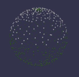
// Build and instantiate meshnodegeo.build();var mesh = nodegeo.createMesh("nodegeomesh");The setPositionsBlock will call the RandomBlock once per vertex to generate the final mesh:
Contextual Values
To go further you may want to READ from the geometry. To do that the system provides several contextual values that are capable of pulling data FROM the active geometry.
The active geometry is the geometry connected to the block that seeks to read contextual values. In our example below, that will be the SetPositionsBlock.
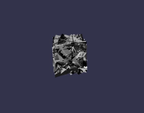
We can rewrite our graph but instead of adding random values directly we can add the normal of each vertex scaled by a random value to the position of each vertex.
The associated code is:
// Create node geometryvar nodeGeometry = new BABYLON.NodeGeometry("nodegeo");
// GeometryInputBlockvar Positions = new BABYLON.GeometryInputBlock("Positions");Positions.contextualValue = BABYLON.NodeGeometryContextualSources.Positions;
// MathBlockvar Add = new BABYLON.MathBlock("Add");Add.operation = BABYLON.MathBlockOperations.Add;
// MathBlockvar Multiply = new BABYLON.MathBlock("Multiply");Multiply.operation = BABYLON.MathBlockOperations.Multiply;
// GeometryInputBlockvar Normals = new BABYLON.GeometryInputBlock("Normals");Normals.contextualValue = BABYLON.NodeGeometryContextualSources.Normals;
// VectorConverterBlockvar Converter = new BABYLON.VectorConverterBlock("Converter");
// RandomBlockvar random = new BABYLON.RandomBlock("random");
// GeometryInputBlockvar Min = new BABYLON.GeometryInputBlock("Min", BABYLON.NodeGeometryBlockConnectionPointTypes.Float);Min.value = 0;
// GeometryInputBlockvar Max = new BABYLON.GeometryInputBlock("Max", BABYLON.NodeGeometryBlockConnectionPointTypes.Float);Max.value = 1;
// SetPositionsBlockvar setpositions = new BABYLON.SetPositionsBlock("set positions");
// SphereBlockvar sphere = new BABYLON.SphereBlock("sphere");
// GeometryOutputBlockvar geometryout = new BABYLON.GeometryOutputBlock("geometryout");
// Connectionssphere.geometry.connectTo(setpositions.geometry);Positions.output.connectTo(Add.left);Normals.output.connectTo(Multiply.left);Min.output.connectTo(random.min);Max.output.connectTo(random.max);random.output.connectTo(Converter.xIn);random.output.connectTo(Converter.yIn);random.output.connectTo(Converter.zIn);Converter.xyzOut.connectTo(Multiply.right);Multiply.output.connectTo(Add.right);Add.output.connectTo(setpositions.positions);setpositions.output.connectTo(geometryout.geometry);
// Output nodesnodeGeometry.outputBlock = geometryout;nodeGeometry.build();var mesh = nodeGeometry.createMesh("nodegeomesh");
Which will generate the following mesh:
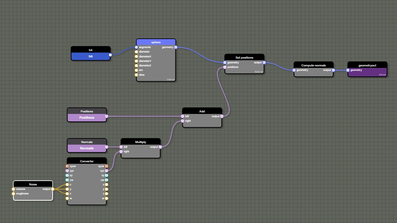
To better understand the graph, here is a visual representation. See the section on the Node Geometry Editor below.
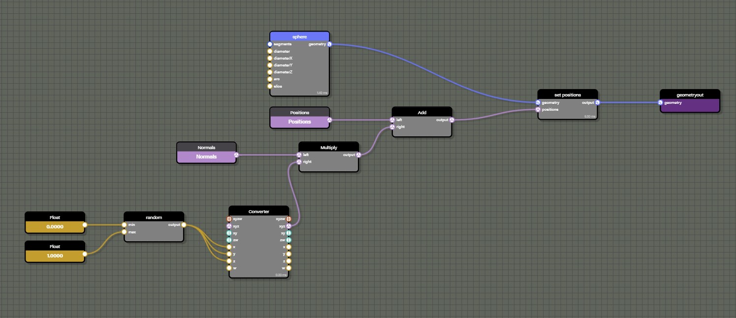
Please note that we used the VectorConverter to produce a Vector3 out of the RandomBlock generating a float.
We are also using the MathBlock twice to get Add and Multiply operations. We also have access to all trigonometry operations with the GeometryTrigonometryBlock.
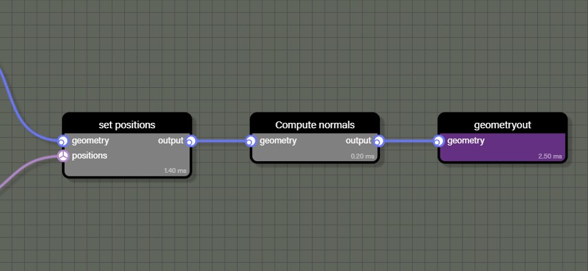
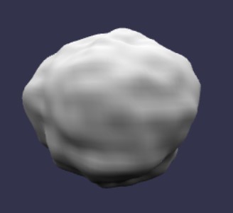
To complete this graph, we need to add a ComputeNormalsBlock to make sure the normals are rebuilt using the new positions:
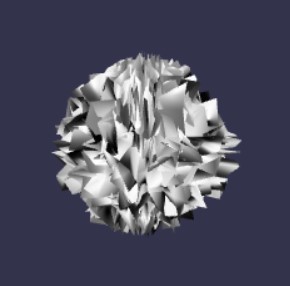
This will produce our weird random based sphere:
The list of available contextual values contains the following:
- positions: Contextual value pointing at the positions array of the active geometry
- normals: Contextual value pointing at the normals array of the active geometry
- colors: Contextual value pointing at the colors array of the active geometry
- tangents: Contextual value pointing at the tangents array of the active geometry
- uvs1: Contextual value pointing at the uvs array of the active geometry
- uvs2: Contextual value pointing at the uvs2 array of the active geometry
- uvs3: Contextual value pointing at the uvs3 array of the active geometry
- uvs4: Contextual value pointing at the uvs4 array of the active geometry
- uvs5: Contextual value pointing at the uvs5 array of the active geometry
- uvs6: Contextual value pointing at the uvs6 array of the active geometry
- vertexID: Contextual value representing the vertex index of the current vertex of the active geometry
Many of the previous contextual values CANNOT be used with the InstantiateOnFacesBlock block. We will detail which of them can be used below.
Node Geometry Editor
As we can see above, creating even a relatively simple NodeGeometry with code can quickly become very long. This is why we introduced a visual tool to help build NodeGeometry graphs.
Instancing Geometries
Ok, now it is time to really unleash the core power of the NodeGeometry!
With the InstantiateOnVerticesBlock class and the InstantiateOnFacesBlock class, you have the opportunity to instantiate a new geometry per vertex - or multiple times per face.
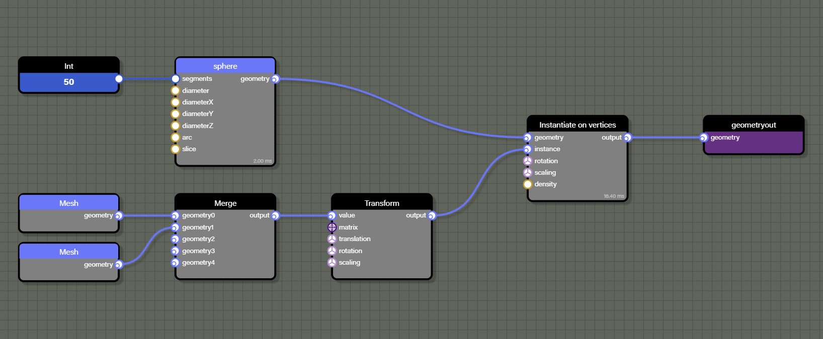
So let's look at this graph:
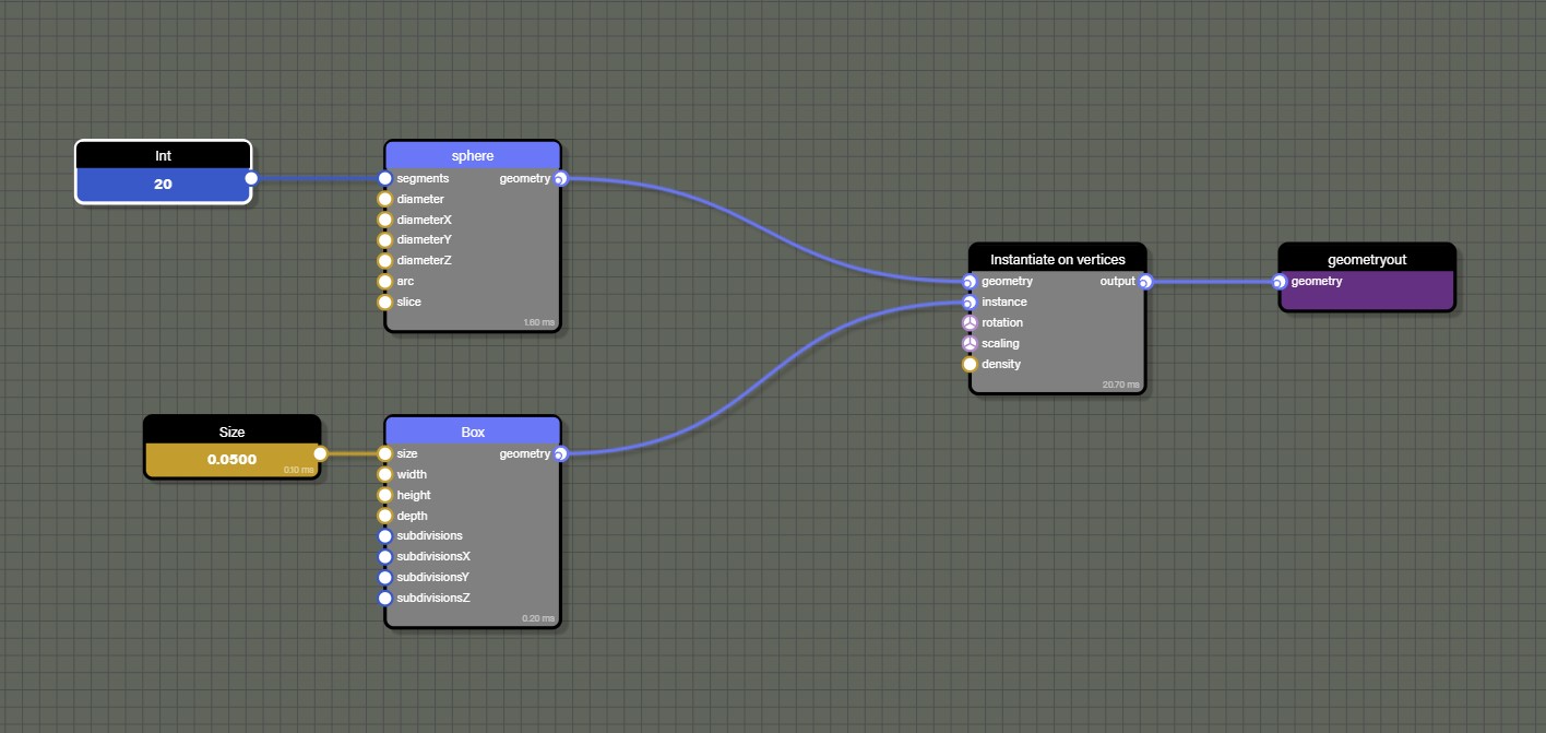
The InstantiateOnVerticesBlock block is used to place a box on each vertex of the sphere:
You can apply rotation or scaling per instance by connecting values to the rotation and scaling inputs.
The density input can be used to affect a percentage of the overall vertices. For example, placing an instance of the box only on 15% of the active geometry's vertices.
The InstantiateOnFacesBlock class works similarly but will generate several instances per face. This block does not have a density input but instead a count input that will let you decide how many instances in total you want to distribute across all faces of the active geometry.
When using an InstantiateOnFacesBlock, you can only use the following contextual values:
- positions: Contextual value pointing at the positions array of the active geometry
- normals: Contextual value pointing at the normals array of the active geometry
- faceID: Contextual value representing the face index of the current face of the active geometry
Controlling the Flow
The ConditionalBlock is the central block if we want to control what is going on with the geometry flow. It can help decide which branch of the node graph to take based on a condition that can be:
- Equals
- Not equals
- Greater than
- Greater or equals
- Lower than
- Lower or equals
- Xor
- Or
- And
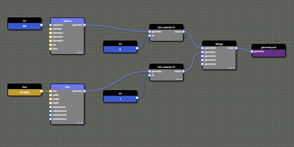
For instance we can decide to have a new sphere made of boxes but we want one hemisphere to use one material and the other hemisphere to use another.
This graph will do it:
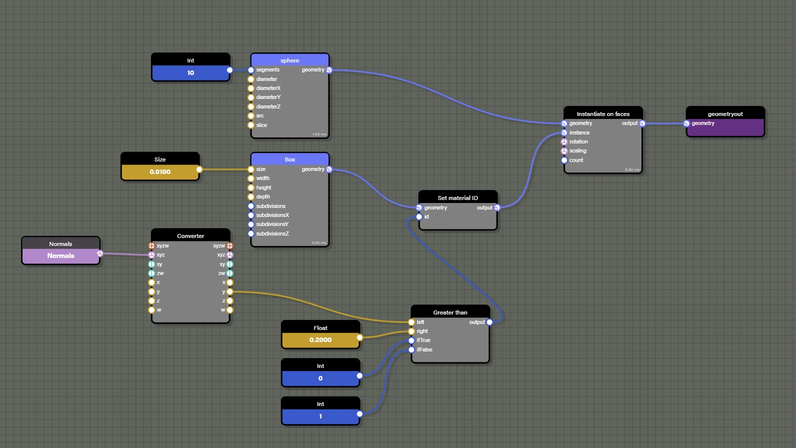
The ConditionBlock is used here with a Greater than setup and will then pick the value 0 or 1 based on the y value of the normal. The normal that is evaluated belongs to the active geometry. In this case, the active geomerty is the sphere as the sphere is the manipulated by the InstantiateOnFacesBlock block. If the y value of the normal is greater than 0.2 then it will pass a value of 0 to the SetMaterialIDBlock. Otherwise it will pass a value of 1.
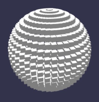
The outcome:
Random and Noise
In order to get random values, we have already seen the RandomBlock. However, there is another one that can be used which is the NoiseBlock.
This block will generate a noise pattern based on a Perlin noise algorithm.
Here is our example again with the SetPositions block:
Which will produce this mesh:
Material ID
If working with multiple mesh sources is desired, we can merge them easily with the MergeBlock:
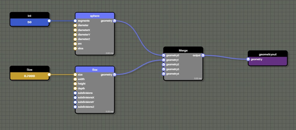
Which will generate this mesh:
The generated mesh will be made of one unified geometry and be rendered with one draw call.
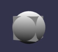
But we can go further and actually attach a material ID per geometry with the SetMaterialID block:
Which will generate this mesh:

The mesh will now have a list of subMeshes in mesh.subMeshes and will be rendered with a MultiMaterial using one material per ID.
Serialization
A NodeGeometry entity can be serialized to a json object:
geometry.serialize(true);The boolean indicates if the geometry produced by the MeshBlock should also be serialized into the json object. Use caution when doing this becuase the resulting json can quickly become very heavy.
To load a NodeGeometry from a json object, call this code:
nodeGeometry.parseSerializedObject(json);If using the Node Geometry Editor instead, NodeGeometry can be loaded directly from our snippet server:
const geometry = await BABYLON.NodeGeometry.ParseFromSnippetAsync("IJA02K#11");Loading and Updating From File
In addition to loading from the snippet server, node geometry can be loaded and parsed directly from local storage. This allows a common node geometry flow to be shared between multiple projects while allowing updates to input parameters or source meshes. Asset Manager is a great way to load node geometry files to your scene and can also be used to load meshes to use with the node geometry at the same time. Simply add a new TextFileAssetTask for each node geometry file that needs to be loaded.
const assetsManager = new BABYLON.AssetsManager(scene);const nodeGeometryFile = assetsManager.addTextFileTask("load my node geometry", "nodeGeometry.json");
// load all tasksassetsManager.load();
Asset Manager has a callback we can use to convert the loaded text into a JSON object and then parse to node geometry.
// callbackassetsManager.onFinish = async (tasks) {    console.log("all tasks successful", tasks);
    // files loaded as text need to be parsed to JSON to use    const nodeGeometryJSON = JSON.parse(nodeGeometryFile.text);
    // parse json object into node geometry    const nodeGeometry = await BABYLON.NodeGeometry.Parse(nodeGeometryJSON);}
Remember that we still need to build the node geometry and then use createMesh to actually render it into the scene. However, before we build the node geometry, now is the time to get any node that may need to be assigned a value like a color, vector, or mesh. There are a few options for finding blocks within the graph such as getBlockByName, getBlockByPredicate, or getInputBlocks. These methods can be used to find specific blocks and set their values.
nodeGeometry.getBlockByName("my_vector").value = new BABYLON.Vector3(1.0, 0.0, 1.0);nodeGeometry.getBlockByName("my_mesh").mesh = myLoadedMesh;Once we are done setting parameters or attaching meshes to our node geometry, we then call build and createMesh.
nodeGeometry.build();const myGeometry = nodeGeometry.createMesh("myGeometry");The order of operations here is important. If node geometry is built and then we try to update any values on the blocks within the graph, no changes will be seen until nodeGeometry.build() is called and we createMesh again. This also means that we can load and build a node geometry and keep it in memory until we need it with a call to createMesh. Or we could dispose of a mesh created from nodeGeometry and simply call createMesh again at a later point to bring the node geometry back into the scene. In this way node geometry acts a little like Asset Container where we always have the it in memory ready to create new meshes whenever we need them.
Optimizations
The NodeGeometry class uses the CPU to process data. Which means that we have to be cautious if expecting to generate several meshes.
For instance let's take this graph:
We can see that the InstantiateOnVerticesBlock will call the Transform of the geometry flow for each vertex of the sphere. Note the use of the MergeBlock to combine multiple geometries. In this case, as nothing in the instance part of the graph is using contextual values - such as reading positions or normals - we can ask the GeometryTransformBlock to not reevaluate its context on each call.
To do so simply call:
myBlock.evaluateContext = false;